HULL UK
HULL
HomeGeophysicsTomografía sísmica de refracción/reflexión

Seismic Tomography for Ground Investigations in Hull

Geotechnical engineering with regional judgment.

LEARN MORE

A common oversight in Hull is assuming a single borehole can map the variable depth to chalk bedrock across a site. The alluvial deposits of the Humber Estuary create rapid lateral changes in soil stiffness, and a point sample often misses buried channels or solution features in the underlying chalk. Seismic tomography overcomes this by generating a 2D or 3D velocity model of the subsurface. Before designing foundations, we typically pair this method with a calicatas exploratorias to confirm stratigraphy in shallow zones, while the tomography resolves deeper contrasts that a pit cannot reach.

Illustrative image of Seismic tomography (refraction/reflection) in Hull
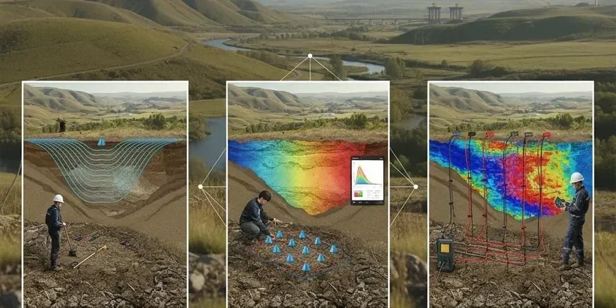
Refraction tomography in Hull's alluvial plain can resolve velocity contrasts as subtle as 15% between soft clay and dense till.

Our service areas

Scope of work

The survey uses a linear array of 24 to 48 geophones spaced at 1 to 3 m intervals, with a sledgehammer or accelerated weight drop as the energy source. In Hull's soft floodplain soils, we prefer a higher source energy — often a 10 kg hammer on a steel plate — to ensure signal penetration past the soft Holocene clays into the glacial till or chalk. The recorded travel times are inverted using refraction tomography for P‑wave velocities and, where shear-wave data is needed, a horizontal geophone component captures S‑waves. This setup is complemented by MASW-VS30 when the project requires a shear-wave velocity profile for seismic site classification under Eurocode 8.
Technical reference — Hull

Area-specific notes

Eurocode 7 (BS EN 1997‑1:2004) and the UK National Annex require that ground investigations characterise variability across the site, not just at borehole locations. Hull's geology — soft alluvium over glacial till over chalk — presents a classic problem: solution features in the chalk can cause sudden subsidence, and buried channels filled with loose sand or gravel create bearing capacity anomalies. Without seismic tomography, these features remain undetected until excavation. The method's ability to image velocity contrasts as low as 10% makes it a cost‑effective way to reduce the risk of differential settlement or foundation failure in this region.

Need a geotechnical assessment?

Reply within 24h.

Email: contact@geotechnical-engineering.biz

Standards used


BS EN 1997‑1:2004 (Eurocode 7 – Ground investigation and testing), BS 5930:2015 (Code of practice for ground investigations), BS 1377‑18 (Standard guide for seismic refraction method)

Technical parameters

ParameterTypical value
Array length48–144 m (24–48 geophones)
Geophone natural frequency4.5 Hz or 10 Hz
Source typeSledgehammer (10 kg) or accelerated weight drop
P‑wave velocity range200–2500 m/s
Depth of investigation15–40 m depending on spread length
Inversion algorithmNon-linear least squares (e.g. Rayfract, SeisImager)
Resolution0.5–2 m cell size in tomogram

Common questions


How deep can seismic tomography investigate in Hull's soils?

With a 48‑geophone array and an accelerated weight drop, we typically achieve penetration depths of 20–35 m in Hull's soft alluvium and till. Where the target is the chalk bedrock (often at 15–30 m depth), a longer spread and higher source energy extend the depth to 40 m.

What is the typical cost range for a seismic tomography survey in Hull?

For a standard linear survey covering 100–150 m of profile, the cost ranges between £2,410 and £4,360 depending on site access, geophone spacing, and the need for shear‑wave acquisition. A detailed quotation is provided after a site walkover.

How does seismic tomography compare to boreholes for detecting voids?

Boreholes provide point data and can easily miss a solution feature in the chalk located between holes. Seismic tomography creates a continuous velocity image across the profile, so a low‑velocity anomaly (indicating a void or weathered zone) becomes visible in the tomogram. We recommend tomography as a reconnaissance tool, followed by targeted boreholes for verification.

Can the method work on Hull's floodplain with high groundwater?

Yes. High groundwater actually improves P‑wave coupling because saturated soils transmit seismic energy more efficiently. We adjust the geophone spike length to ensure good contact in soft, wet ground. The main challenge is avoiding surface wave interference, which we mitigate by increasing the source offset and applying appropriate filtering during processing.

Location and service area

We serve projects across Hull.

Location and service area